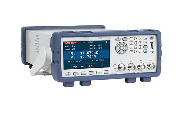
Various problems that are prone to occur in the use of lithium iron phosphate batteries are often reflected in the increase of internal resistance. The level of internal resistance can characterize the deterioration of the battery, and the internal resistance test has become one of the most critical, fastest and most effective methods to measure the quality of the battery.
At present, the research on the internal resistance of lithium-ion batteries has the following problems:
1. The internal resistance of lithium-ion batteries is usually very small, generally in the order of milliohms, and it is also an active component, which is different from general resistance components and cannot be directly measured;
2. The internal resistance of the battery is easily affected by the state during the test. For example, under different ambient temperatures and different states of charge, the internal resistance of the battery has a certain difference.
1. Introduction to Internal Resistance Test Standards
The International Electrotechnical Commission (IEC) is the most important international standard-setting body for lithium-ion batteries, and the performance standard for lithium-ion batteries IEC 61960-3:2017 <Lithium batteries and battery packs containing alkaline or other non-acid electrolytes for portable applications Batteries and accumulators - Part 3: Square and cylindrical lithium accumulators and accumulators made of them > and IEC 62620:2014 < accumulators and batteries containing alkaline or other non-acid electrolytes Secondary lithium cells and accumulators for use in industrial applications There are test items required to test the internal resistance of the battery in the group >.
The Japan Industrial Standards Survey (JISC) is the national standardization management organization in Japan, and the standards issued include JISC 8715-1:2018 <Industrial Secondary Lithium Batteries and Storage Batteries. Part 1 Performance requirements and tests >.
2. Test principle
The test methods recommended by the three standards, IEC 61960-3:2017, IEC 62620:2014, and JISC 8715-1:2018, include both the AC test method and the DC test method.
The AC test method is to add a small-amplitude AC signal as excitation at both ends of the battery, and obtain the internal resistance value by measuring its voltage response. The DC test method is to force a short-term constant current to the battery. At this time, the voltage of the battery changes with time. If the current passing through the battery is I, the change of the battery voltage is measured in a very short period of time as ΔU. According to ohms The law R=ΔU/I can calculate the DC internal resistance of the battery.

2.1 Applicable objects
IEC 61960-3:2017 stipulates that the AC test method and DC test method are only applicable to battery packs; while IEC 62620:2014 and JISC 8715-1:2018 stipulate that the AC test method is only applicable to cells, and the DC test method is applicable to cells and Battery.
2.2 Specimen requirements
IEC 62620:2014 divides the samples into four types according to the difference in rate discharge capacity: ultra-low rate type (S), low rate type (E), medium rate type (M), high rate type (H), four types. The maximum continuous discharge current of various types of samples at 25°C is usually not lower than the following values: 0.125C, 0.5C, 3.5C, 7.0C.
JISC 8715-1:2018 divides the samples into four types: ultra low magnification type (S), low magnification type (E), medium magnification type (M), high magnification type (H). The maximum continuous discharge current at ℃ shall not be lower than the following values respectively: 0.125C, 0.5C, 3.5C, >3.5C.
IEC 61960-3:2017 does not specify the test specimen.
3. Test procedure
3.1 Test Preparation
The IEC 61960-3:2017 standard stipulates that the battery is fully charged before the internal resistance test and left for 1~4h; the IEC 62620:2014 standard stipulates that the battery is fully charged before the internal resistance test, and then discharges 50%±10% of the rated capacity After standing for 1~4h; JISC 8715-1:2018 requirements are the same as IECIEC 62620:2014.
3.2 Test temperature
IEC 61960-3:2017 specifies the internal resistance test at 20℃±5℃; IEC 62620:2014 and JISC 8715-1:2018 specifies the internal resistance test at 25℃±5℃.
3.3 Test method
IEC 61960-3:2017 stipulates that if it is necessary to use the AC method and the DC method to measure the internal resistance at the same time, the AC method should be used first, and then the DC method should be used. There is no need to charge and discharge the battery between the AC method and the DC method test. The other two standards do not specify the sequence of AC and DC tests.
3.3.1 AC Internal Resistance Test
The AC internal resistance test method specified in IEC 61960-3:2017, IEC 62620:2014 and JISC 8715-1:2018 is the same: apply an AC current with a frequency of 1.0 kHz±0.1 kHz and an effective value of Ia at both ends of the battery for 1~5s signal, measure the AC RMS voltage Ua, and the calculation formula of the AC internal resistance Rac is: Rac=Ua/Ia.
3.3.2 DC resistance test
IEC 61960-3:2017 stipulates that the battery pack is discharged at a constant current of I1=0.2C(A) for 10s±0.1s, and then instantaneously increases the discharge current to I2=1.0C(A) and discharges for 1s±0.1s; while IEC 62620:2014 And JISC 8715-1:2018 stipulates different discharge current according to the type of battery, and the specific current value is shown in Table 1.
In addition, the two discharge times specified in IEC 62620:2014 and JISC 8715-1:2018 are longer than those in IEC 61960-3:2017, which are (30±0.1)s and (5±0.1)s respectively.

