

What is an inverter?
Inverter is a converter that converts DC power (battery, storage battery) into fixed-frequency, constant-voltage or frequency-modulated alternating current (generally 220V, 50Hz sine wave). It is composed of inverter bridge, control logic and filter circuit.
It is widely used in air conditioners, home theaters, electric grinding wheels, electric tools, sewing machines, DVDs, VCDs, computers, TVs, washing machines, range hoods, refrigerators, video recorders, massagers, fans, lighting, etc.
The popularity of automobiles is relatively high. When going out to work or traveling, you can use inverters to connect batteries to drive electrical appliances and various tools to work. The car inverter output through the cigarette lighter is 20W, 40W, 80W, 120W to 150W power specifications.
More power inverter power supply should be connected to the battery through the connecting wire. Various electrical appliances can be used in the car by connecting household appliances to the output end of the power converter. The electrical appliances that can be used are: mobile phones, laptops, digital cameras, cameras, lights, electric shavers, CD players, game consoles, handheld computers, power tools, car refrigerators, and various travel, camping, and medical emergency appliances Wait.
working principle
Inverter is a DC to AC transformer, it is actually a voltage inversion process with the converter.
Inverter (Figure 1) The converter converts the AC voltage of the grid into a stable 12V DC output, and the inverter converts the 12V DC voltage output by the Adapter into high-frequency high-voltage AC; both parts are also used More used pulse width modulation (PWM) technology. The core part is a PWM integrated controller, the Adapter uses UC3842, and the inverter uses the TL5001 chip. The operating voltage range of TL5001 is 3.6~40V. There is an error amplifier, a regulator, an oscillator, a PWM generator with dead zone control, a low-voltage protection circuit, and a short-circuit protection circuit.
Input interface part: The input part has 3 signals, 12V DC input VIN, working enable voltage ENB and Panel current control signal DIM. VIN is provided by the Adapter, and the ENB voltage is provided by the MCU on the motherboard, and its value is 0 or 3V. When ENB=0, the inverter does not work, and when ENB=3V, the inverter is in normal working state; and the DIM voltage Provided by the main board with a range of 0~5V. Different DIM values are fed back to the feedback terminal of the PWM controller. The current provided by the inverter to the load will also be different. The smaller the DIM value, the current output by the inverter. The bigger.
Voltage start circuit: when ENB is high,
The inverter outputs high voltage to light the panel's backlight tube.
PWM controller: It has the following functions: internal reference voltage, error amplifier, oscillator and PWM, overvoltage protection, undervoltage protection, short circuit protection, output transistor.
DC conversion: The voltage conversion circuit is composed of a MOS switch tube and an energy storage inductor. The input pulse is amplified by a push-pull amplifier and then drives the MOS tube to switch, so that the DC voltage charges and discharges the inductor, so that the other end of the inductor can get AC Voltage.
LC oscillation and output circuit: to ensure the 1600V voltage required for the lamp to start, and to reduce the voltage to 800V after the lamp is started.
Output voltage feedback: When the load is working, the sampled voltage is fed back to stabilize the voltage output of the I inverter.
Whether in remote villages, field needs or power outage emergency, inverters are a very good choice. The most common one is the UPS power supply used in the computer room. In the event of a sudden power failure, the UPS can invert the DC power in the battery to AC for use by the computer, thereby avoiding the problem of data loss caused by the sudden power failure.
This article will introduce two relatively simple inverter circuit diagrams. A simple inverter circuit diagram is attached to clarify that if interested friends can study and make an inverter by themselves, it is indeed a very fulfilling thing. One is a more common inverter circuit diagram
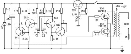
The above is a relatively easy to manufacture inverter circuit diagram, which can invert 12V DC power supply voltage to 220V mains voltage. The circuit is driven by a multivibrator composed of BG2 and BG3, and then driven by BG1 and BG4 to control BG6 Work with BG7. The oscillating circuit is powered by the stabilized power supply of the BG5 and DW group, which can make the output frequency relatively stable. At the time of manufacture, the transformer can be selected with a common mains transformer with dual 12V output. The appropriate 12V battery capacity can be selected according to requirements.
The following is an electrical diagram of a high-efficiency sine wave inverter. The circuit is powered by a 12V battery. First use a voltage doubler module to double the voltage to power the op amp. Can choose ICL7660 or MAX1044. Op amp 1 generates a 50Hz sine wave as the reference signal. Op amp 2 acts as an inverter. Op amp 3 and Op amp 4 are used as hysteresis simulators. In fact, the operational amplifier 3 and the switch tube 1 constitute a proportional switching power supply. Op amp 4 and switch tube 2 are the same. Its switching frequency is unstable. When the output signal of the op amp 1 is positive phase, the op amp 3 and the switch tube work. At this time, the output of op amp 2 is negative phase. At this time, the potential (constantly 0) of the positive input terminal of the op amp 4 is always higher than the potential of the negative input terminal, so the output of the op amp 4 is always 1, and the switch is turned off. When the output of op amp 1 is negative, the opposite is true. This completes the alternate work of the two switch tubes.
When the reference signal is higher than the detection signal, that is, the signal at the negative input terminal of the op amp 3 or 4 is higher than the signal at the positive input terminal by a small value, the comparator outputs 0, the switch is turned on, and the detection signal progresses rapidly. When the signal is a small value higher than the reference signal, the comparator outputs 1 and the switch is turned off. It should be noted here that the simulator has a positive reaction process when the circuit is flipped, which is the characteristic of the hysteresis simulator. For example, under the premise that the reference signal is lower than the detection signal, as their differences approach from time to time, when they are equal, the reference signal is immediately higher than the detection signal by a certain value. This "certain value" affects the switching frequency. The larger it is, the lower the frequency. Choose it here as 0.1~0.2V.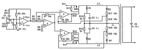
The function of C3 and C4 is to allow the freewheeling current of the switch with higher frequency to pass through, and produce larger impedance to the 50Hz signal with lower frequency. C5 is calculated by the formula: 50=. L is generally 70H, it is best to measure it when manufacturing. Thus, C is about 0.15μ. The ratio of R4 to R3 should be severe and equal to 0.5. If it is larger, the waveform will be distorted obviously, and if it is smaller, it will not start to vibrate, but it is better to be larger than smaller. The maximum current of the switch tube is: I==25A.
Existing inverters have two types: square wave output and sine wave output. Inverters with square wave output have high efficiency. Regarding appliances designed with sine wave power supplies, most appliances can be used except a few appliances that are not applicable. Inverters with sine wave output do not have this defect, but there are Inefficient defects
JUNLEE Group is an integrated full power energy factory that specializes in Uninterruptible Power Supply (UPS), Lead-Acid Battery, Battery pack, EV battery, Energy Storage Battery, Energy storage power station, Power pack Gel battery, PV Inverter and Solar system.
Production capacity reach 200000 KVaH per month. Products apply to Electric vehicles,electric mobility, solar & wind energy storage system, UPS, backup power, telecommunication, medical equipment and lighting.
JUNLEE sets up "Power research center" with more High-tech products.More than 100 engineers provided in-time and efficient one-stop solutions.
They mission strives to bring green power to the world.
To learn more about Li-ion batteries, please refer to https://www.junleepower.com/