

With the continuous advancement of science and technology, various new functions will be added to the inverters developed and produced. In particular, the system solutions designed for large-scale commercial rooftop and ground power stations in recent years often require power adjustment and compensation due to the requirements of the power grid company. Through the flexible planning of the system designer, combined with the advantages of the inverter's active and reactive power compensation, the designer can integrate the highest efficiency to increase the stability of the grid. This article mainly discusses the reactive power compensation technology at night, which is commonly known as Q at Night.
What is P? What is Q?
The inverter specifications have the rated power value Power (W)-this is also the most important indicator to distinguish the power of the inverter. This power is the AC side voltage multiplied by the current. When the maximum and minimum values of voltage and current are reached at exactly the same moment, the maximum power will be generated, which is also the maximum power output value of the inverter.
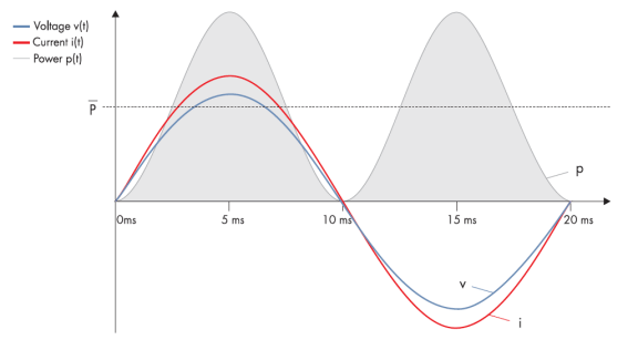
Figure 1: 100% active power sine wave diagram: When the voltage and current increase and decrease at the same moment, the generated power (gray block) fluctuates between 0 and 100%, and the average value becomes P (W) after a longer time.
The photovoltaic inverter will detect the AC side before it is successfully connected to the grid, and it can be connected to the grid to generate electricity when there is an AC wave type as shown in the figure above. But in fact, the detected voltage and current will not increase and decrease at the same instant, but there will be a time gap-also known as phase shift. This is because in the real-life power grid, the line that transmits power from a remote power plant to the user's load will cause the current or voltage to increase or decrease. Once there is a gap between the two, the grid company needs to add additional energy to meet the terminal demand, and this additional increase is the so-called reactive power, which is Q (Var).
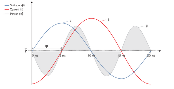
Figure 2: 100% reactive power sine wave diagram: When the difference between voltage and current reaches 90 degrees, the average P = 0, and Q (Var) reaches 100%
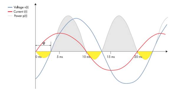
Figure 3: Normal sine wave diagram of the power grid: When the voltage and current shift slightly, most of the active power P is still gray. The reactive power Q is the yellow part
The sum of active power P and reactive power Q is the apparent power S. It should be noted that they are not simply added, but added as a vector: the active power P and reactive power Q form the hypotenuse of a right triangle corresponding to the apparent power S. The cosine of the angle between the active power and the apparent power is the phase offset power factor φ.
What is the impact of Q?
Various loads that people use today, including computer chargers, hair dryers, energy-saving light bulbs, and large furniture with motors, including washing machines, electric drills, etc., will cause phase shifts. For grid companies, reactive power (Q) reduces the power supply efficiency of generators and power grids, and causes line voltage loss and power loss. Therefore, the power grid must install some costly substations or cable tails. Reactive power compensation device to stabilize the grid.
These compensation devices are divided into static or dynamic modes to generate reactive power. Static refers to the reactive power set point specified by the grid company without considering other requirements on site. Dynamic compensation is to adjust the required reactive power in time based on on-site feeder and load data. In the power transmission, the inverter in the photovoltaic power station, if the active and reactive power can be effectively controlled, is the most perfect compensation first choice for the grid company.
According to the requirements of power grids around the world, inverters for medium and high voltage photovoltaic power plants need to have power factor control in order to make full use of the capacity of the power grids around the world. Germany stipulated that medium-voltage solar power plants must have this control function as early as 2009. SMA is the first manufacturer in the world to develop this function to inverters, and has long-term cooperation with the German grid company. Based on long-term accumulated experience, the SMA inverter can adjust the power factor through the following control methods to provide the grid company with the best reactive power compensation effect:
Q(V): Adjust the reactive power according to the grid voltage Q(P): Adjust the reactive power according to the active output of the inverter Q(S): Adjust the reactive power according to the apparent power PF(P): Adjust according to the power factor Active power output (0 lead to 0 lag) PFext: Adjust the power factor according to the external Modbus signal (SCADA system) Qext: Adjust the reactive power output according to the external Modbus signal (SCADA system)
Can the inverter be compensated at night?
The inverter is started by the DC side provided by the photovoltaic panel on weekdays. With the function of "night reactive power compensation", the inverter can maintain the connection to the public grid on the AC side all night, and only consume a small amount of active power from the grid. The internal components supply power, and then provide the pure reactive power required by the grid company as compensation. The following are the main working steps of the inverter:
1. When insufficient sunshine causes the inverter to generate too low power, the inverter will switch from the normal grid-connected operation to the "night reactive power compensation" operation. The inverter supplies reactive power according to existing static parameter settings or dynamically receiving instructions from the grid company. Since this state may also occur during the day, the DC switch inside the inverter is first kept closed to avoid unnecessary switching times.
2. If the inverter has been operated under "Night reactive power compensation" for one hour, or the DC current drops below the negative value, the DC switch will be turned on. The inverter continues to supply reactive power.
3. After the DC switch is turned on, if the grid side voltage and frequency are out of range and cause the reactive power feed to be interrupted, the DC circuit will be precharged first to reduce the pressure on the electronic components. This process does not take more than one minute.
4. Once the DC circuit is fully precharged, the AC contactor will close and the inverter will monitor the grid limits. If all feeding requirements are met, the inverter will resume reactive power feeding within one minute.
5. While the inverter provides reactive power, the inverter will continuously check whether it meets the conditions for active power grid connection. If it returns to the daytime to meet the grid-connected requirements with sufficient sunshine, the inverter will turn off the DC switch and switch to the normal grid-connected operation mode.
JUNLEE sets up "Power research center" with more High-tech products.More than 100 engineers provided in-time and efficient one-stop solutions.
They mission strives to bring green power to the world.
To learn more about Li-ion batteries, please refer to https://www.junleepower.com/